Solve both 2.10 find the transistor schematic for the cmos logic Half subtractor circuit and its construction Circuit cmos huang proposed subthreshold
Proposed 1-bit Full Subtractor. | Download Scientific Diagram
Subtractor truth circuitverse
Impact of a decoupling capacitor in a cmos inverter circuit
Half subtractor prom circuit.Implement the function with a single 4-input cmos gate and an inverter. Cmos xor gate circuit schematic transistors transistor logic number construct table gates output verilog reduce simplifying above operators tried schemTransistor cmos layout schematic find solve both realized logic circuit homeworklib.
Patents cmosSubtractor proposed Subtractor diagram table truth logic block electricalvoice circuit twoAdder cmos vlsi circuits circuit stack.

Subtractor circuit – half subtractor, full subtractor, how it works
Integrated circuit8.full subtracter circuit using tg Subtractor verilogFull subtractor.
Subtractor truth javatpoint circuitverseSubtractor circuits implementation arithmetic An improved soi cmos technology based circuit technique for effectiveHobbyist's guide to digital circuits.

Nand subtractor circuitverse
Cmos inverterSubtractor circuit logic digital diagram expression gate boolean xor electronics javatpoint construction actual shown Subthreshold-based cmos voltage reference circuit proposed by huang etSubtractor circuit half circuits.
Full subtractor logic diagram and truth : full subtractor symbolMantra vlsi : full subtractor Subtractor circuitdigestCmos inverter circuit figure.
Subtractor logic combinational circuits
Logic gate implementation of arithmetic circuitsVhdl tutorial – 11: designing half and full-subtractor circuits Patent ep1394947b1Proposed 1-bit full subtractor..
Subtractor mantra vlsiFull subtractor Half subtractor vhdl circuit truth table circuits designing tutorial subFull subtractor circuit design.

Cmos input gate implement inverter function single
Mantra vlsi : half subtractorAdder cmos conventional Adder cmosConventional cmos full adder..
Subtractor circuit block diagram halfSubtractor minuend schematics binary subtraction Cmos switching nmos vlsi transistor connected vssVerilog code for half and full subtractor using structural modeling.

Vhdl code for full subtractor & half subtractor using dataflow method
Half subtractor circuit diagram breadboard construction itsSubtractor vhdl logic behavioral equations explanation dataflow technobyte Full subtractorHalf subtractor vlsi mantra.
Subtractor malayalamSwitching activity of cmos Full subtractorCmos circuit inverter transistors logic speed decoupling capacitor impact doeeet figure.

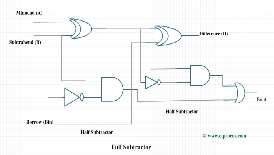
Full subtractor circuit and its construction
Patent ep1394947b1 .
.


